


LED Cube Update - Firmware
I've made some serious progress on the LED cube so I figured it was time for an update post. When I left off on the first LED Cube post I had a functioning cube, but no supporting circuitry to drive it. This post will cover the ins and outs as well as the ups and downs of the driver circuit construction all the way up through the firmware engine to display animations.
Microchip had been good enough to send me a sample of their ATSAMD20E16A-ANT Cortex M0+ microcontroller (MCU) and I was excited about developing on an ARM micro. As I perused the datasheet I came across my first issue. The maximum operating voltage of this line of ARM chips is 3.6V which is pretty close to the forward voltage of my LEDs at 20mA. This doesn't leave much overhead for losses inside the MCU or current limiting resistors, but LEDs can still be acceptably bright at less than optimal forward voltages so I kept looking. Then I found my big issue, using the highest current settings each pin can only source 7mA or sink 10mA of current. Even at full voltage 10mA was just not going to be enough current for this large an array. It would just never be bright enough.
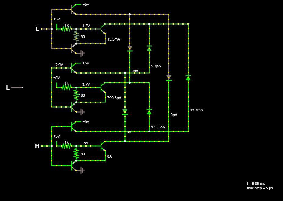
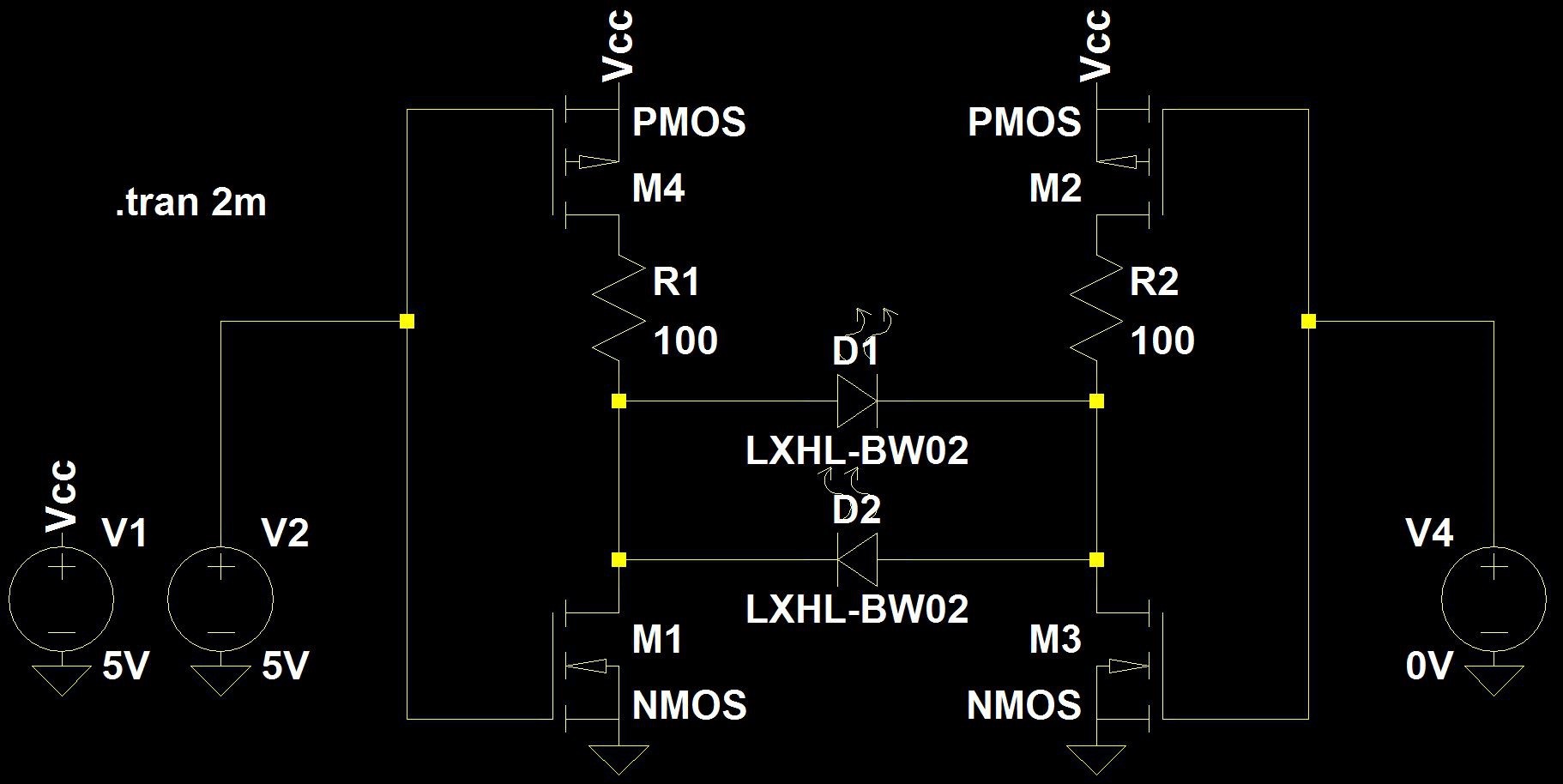
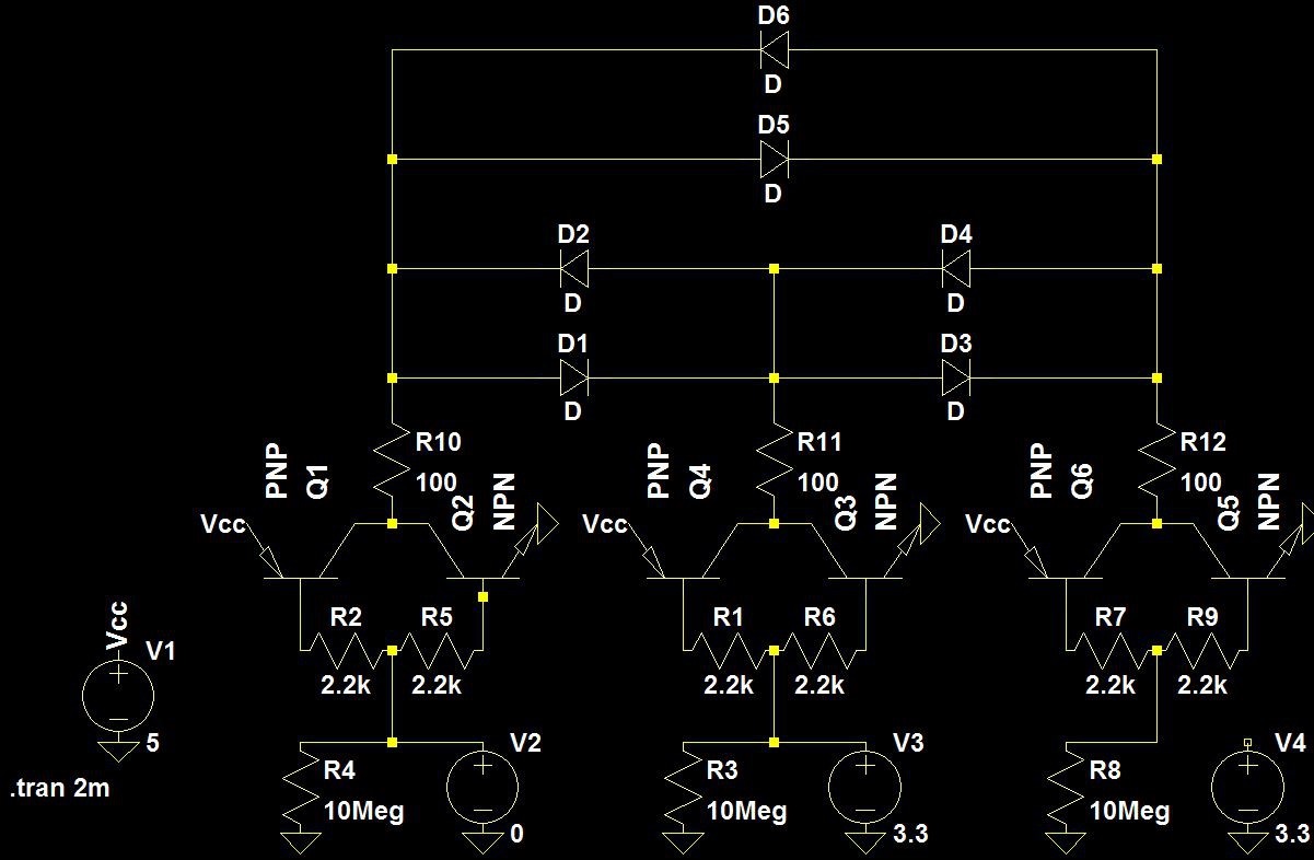
The tri-state behavior of an MCU's I/O pins is what makes charlieplexing possible. When a pin is set to be an input it presents to an external circuit as a high resistance path to ground (or Vdd) the draws an extremely low amount of current. This is what allows me to isolate only the LED that I want to turn on. The need to preserve the tri-state behavior is why I couldn't just whack a single transistor on the output pin and use that to drive the ~20mA of current that I need through each cube pin. Not wanting to give up on the ARM MCU yet I attempted to design a tri-state buffer that functions using just one input. If I had done some more research before breadboarding I might have realized that plan would never work, but instead I grabbed a bunch of different types of transistors discovered several ways not to build a tri-state buffer.
After thoroughly proving that the ARM MCU was not the right micro for the job I looked at what I had and found an ATmega328P. These MCUs, well known from their use in the original Arduino, can handle 40mA per pin, run plenty fast for my purposes, and have a ton of example code floating around the internet. It may not be shiny and new like the Cortex based MCU, but the 328P is certainly up to the task at hand.
While I was deep into my efforts to invent discrete tri-state circuits that don't actually work, I decided to throw together an Arduino sketch just to see the cube do something. It wasn't particularly impressive, but it did work and that was nice to see. A video of my first animation test can be seen below.
The combination of Arduino overhead and the "for loop tax" meant that I had a lot of wasted instruction cycles where no LEDs were turned on. After connecting my oscilloscope to the cube it seemed like at best I was getting a 25% duty cycle meaning that the cube was completely off for 75% of the time. The video looks alright because there are very few other light sources to compete with, but to the naked eye the LEDs were pretty dim so the low duty cycle didn't surprise me.
The first thing I should mention about my firmware is that I combed through Asher Glick's Charliecube project (https://aglick.com/charliecube.html) quite a bit to see how he did things. I went a different direction, but looking at his code saved me a bunch of development time. I will open source my code in a similar fashion once I'm a bit happier with it.
Once I started developing the core loop on the ATMega the first thing I did was to move to iterating through the cube with pointers rather than loops. This is much more instruction inefficient than iterating with loops, but still leaves an array available for direct access for changing frames and things of that nature. I used a header to define a lookup table describing the construction of the cube. In reality this should probably be a compiler macro, but that level of optimization is a bit far down the line at this point.
I wanted a container for all of the details on each LED so I starting with the defining an LED structure. The assets of each LED are mostly very small values. The anode and cathode pin number can be 1-9 and the intensity level will have a range of 0-15 so I declared all three of those variables to only need a size of 4 bits to save space. The last variable in the struct is a pointer to the next LED in the cube. With a structure to describe the LEDs I initialized one array of LEDs to hold all of the cube's information and an LED pointer that will point to the current LED. I also defined a helper function to initialize the cube by setting the level of all the LEDs to 0, assign the pin numbers from the lookup table in the header file, set the address of the next LED pointers, and then point the currentLED pointer to the first LED in the array.
The majority of the main operational loop is handled by interrupt service routines (IRSs). As the main timer ticks along with the system clock one ISR turns on the next led and one ISR turns that LED off that the appropriate time. I also use the timer overflow ISR to keep track of how long the current image has been shown. The overflow ISR just increments a counter at this time and will be used later to drive animations. At this point I'm just trying to create a critical loop that runs well so the images displayed aren't that interesting. An animation engine will be a later step in the process.
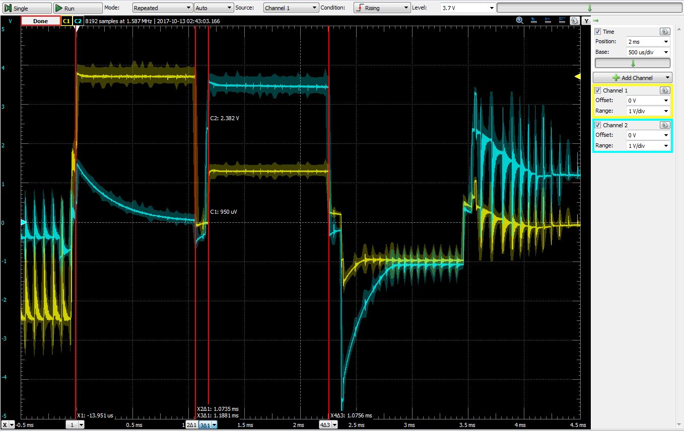
The ATmega328P is shipped from the factory set to run at 1MHz. With very few wasted instructions this would be close to fast enough to drive the cube at 60fps so I started my development using the default speed. Unsurprisingly, this isn't close to fast enough. It takes something like 160 instructions from when the off ISR's timer value is set before it can trigger. This means that for 4-bit dimming an intensity of 1 should keep the LED on for something close to 160 instruction cycles. Using 160 cycles per step of intensity would require 2400 cycles per LED. At 1MHz this would take 2.4ms. For a cube of 64 LED this makes my theoretical minimum refresh rate 1/(2.4ms*64) = 6.5fps which is just unacceptably slow. Below are some traces I captured during this discovery process. The timing setting for these traces is somewhere between having 4-bit dimming working (it wasn't) and having the cube run at 30fps (it was more like 15fps). It became obvious that this isn't a workable system clock speed, so I moved on from this solution.


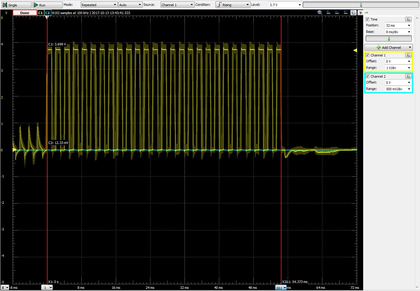
In case you feel the need to see just how unacceptable this frame rate is here is a video. The blinking is not an artifact of the camera's shutter, that's what it looked like in person.
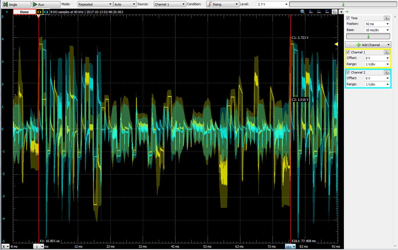
The ATmega328P's internal oscillator runs at 8MHz, but it ships with a prescaler of 8 to achieve the default 1MHz. All I had to do was remove the prescaler to change the system clock to 8MHz without the use of external devices (the chip can go up to 20MHz with an external crystal). This made all the difference. I was able to dedicate 2048 instruction cycles for full LED intensity which is not quite 160 cycles per step of intensity, but is a nice round binary number. At this faster system clock an LED at full intensity is on for 256μs. This gives me a theoretical minimum refresh rate of 1/(256μs*64) = 61.0 fps which is right in line with my goal. 2400 cycles per LED would give me something closer to 52 fps which would be acceptable, but less than I had hoped for and inefficiencies in my code will only make that number lower in real life. From the images below you can see that at this point, not only had I improved my probing strategies, but the cube is operating pretty close to my calculated performance timings.


It's all well and good for the cube to fit the pen and paper model, but how does it look in real life? In the video below I have the cube set to keep each individual LED on for 8 timer overflow cycles or ~1/16th of a second. It may not be completely obvious, but each LED appearing to turn on and stay on despite having turned on and off 32 times is exactly what I'm aiming for. Things are looking up for the happy little cube.
Now that I can get the LEDs turning on fast enough it's time to focus on turning them off even faster. In most LED driver circuits (including this one) an LED is essentially either all the way on or completely off. The way to make them appear dimmer is to use Pulse Width Modulation (PWM) to reduce the duty cycle so that the LED is on for a reduced amount of time. If the modulation is fast enough (~>30fps) this will fool the eye into appearing like the LED is on the whole time, but at a proportionately lower intensity. The way I implemented this was when I set the time to move to the next LED I take the number of instruction cycles per LED and multiply that by the ratio of the intensity level plus one divided by 16 (level 1 => 2/16, level 2 => 3/16, etc...) and set that time as the trigger for the ISR that turns off the current LED. Integer division is not always the best solution, but for this routine worst case is that truncation of the result causes an LED to turn off .125μs early. Using this method the higher priority ISR (next LED on) handles turning off the current LED when it is at full intensity and the lower priority ISR (current LED off) "dims" the LED without wasting instructions for any intensity below 15. Because of this my refresh rate is more or less unaffected by the additional computation. Below is a video of all of the LEDs in the cube sweeping from intensity 1 to intensity 15. 4-bit dimming isn't exactly smooth, but the LEDs aren't flickering so it seems like my LED driver framework is very close to complete.
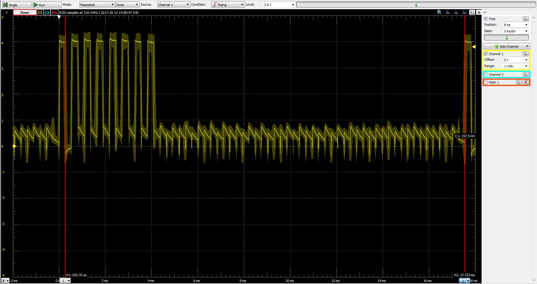
Here is a video of my oscilloscope while probing one of the pins during the dimming test. You can see the duty cycle increase while the LEDs are increasing in intensity.
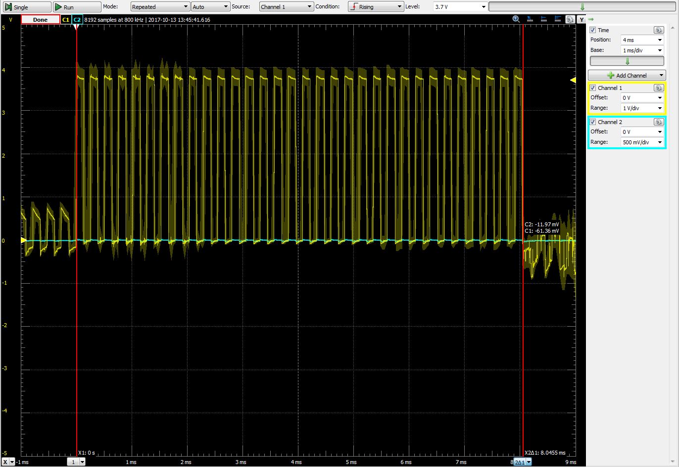
Below you can see a scope trace of two LEDs for the whole dimming sequence. This 2 second sweep is really slow compared to the PWM frequency of the LEDs, especially for the lower intensities where the LED is only on for tens of microseconds at a time. This causes the analog-to-digital converter in my oscilloscope to average the PWM output in much the same way the human eye averages the LED's intensity. This makes the 15 different intensity levels distinct from one another and identifiable on the trace. This breaks down a bit at the higher intensities as the pulse width gets larger and the ADC is able to more faithfully represent what is actually happening, but it's not too difficult to make out the 15 separate intensity steps. The oscilloscope software's attempt at a digital phosphor doesn't help visibility much, but I like this trace because it illustrates what the eye is seeing better than a more high performance scope would.
Sweeping trace of dimming test sequence
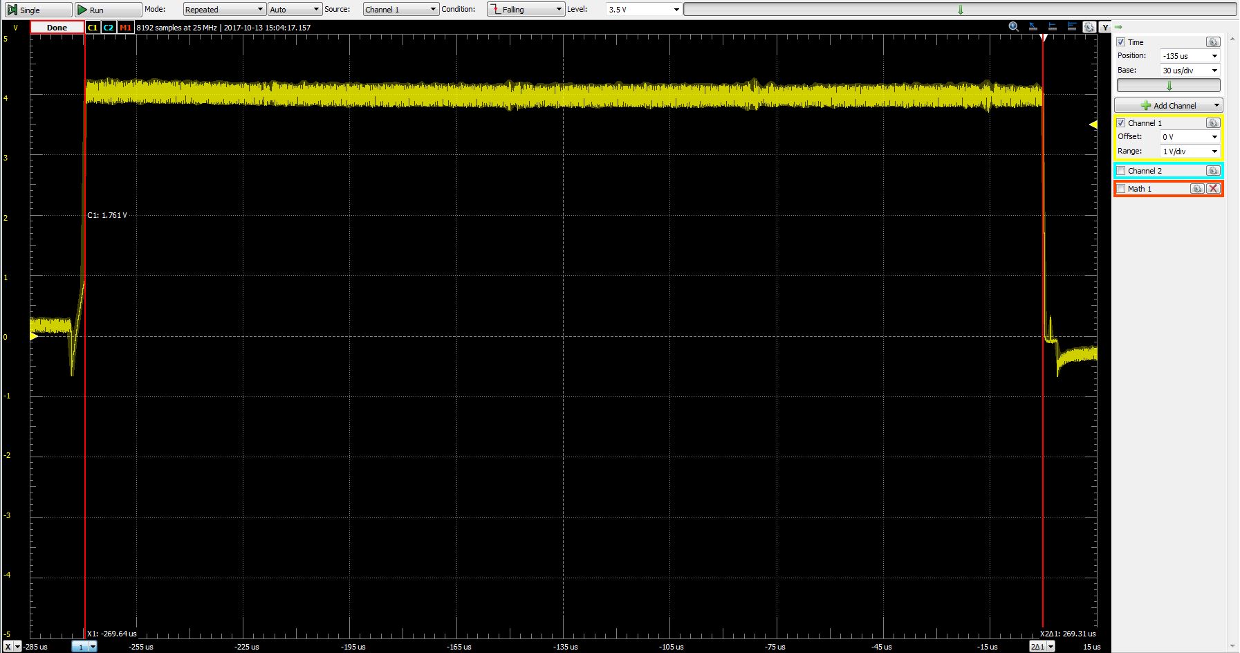
To ensure that my core system was working well, I measured the voltage across a current limiting resistor. There was a bit of variation in the voltage drop as a result of tolerances across the LED batch, but the average drop across the 41Ω resistor was around 615mV. This means the current through the LEDs is around 615mV/41Ω = 15mA which is right where I want it.

Trace across 41Ω current limiting resistor
So whats next? There are two ways to go, optimizing what I have or moving on to animations with a less than perfect functional foundation. With the Hackaday Superconference just three weeks away it's time to start prioritizing. I would love to keep thinking about the hardware and the core loop: testing the pros and cons of overdriving the LED for increased brightness, optimizing system clock, chasing down every wasted instruction. But that is probably not the best use of my time. Currently the cube gets stuck in an infinite loop if no LEDs are on. Once I solve that bug in the core loop, I probably need to move on to the animation engine so I can have a reasonably interesting set of animations to show. I would like to dead bug the entire thing onto a 9V battery holder so I don't have to bring a breadboard for the cube, and soldering that up will be no small task. Guess I better get to it!
I am documenting this project on Hackaday.io as well. I will post large advancements in the work here, but for smaller, closer to day-to-day updates follow the project over on Hackaday.

